
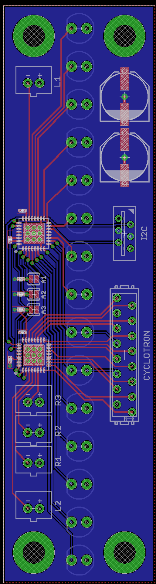
Just finished the layout for the Positron Proton Pack Kit’s powercell!
The mounting holes have the same spacing as on the original powercell, but they’re now mirrored on the other side as well.
The cyclotron’s RGB LEDs are attached directly to the powercell via a 16 pin ribbon cable with a new low profile connector, which is polarized so it can’t be plugged in the wrong way.
There are also five locations for optional JST connectors for the rib LEDs, as seen on the video game pack. These connectors are also polarized.
The powercell connects to the positron via the FFC connector labeled I2C. The cable will only mate with the contacts on one side, so it too protects against accidentally plugging the cable in the wrong way.
A1, A2, and A3 are solder jumper pads for setting the address of the board. You won’t need to change these, as the board will have the correct default address for the kit, but if I ever need to add another powercell to someone’s kit, these pads allow the two to be addressed individually if need be.