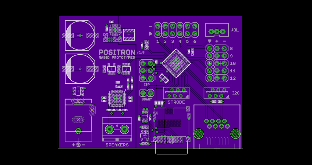
Now this is a story all about how my PCB got flipped, turned upside-down!
I was putting the finishing touches on the Positron’s layout the other day when I decided to fix something that was nagging me for quite a while.
When I began working on the Positron, I placed the power connector along the bottom of the board near the 5V regulator. This location made a lot of sense, both from a power distribution standpoint, and because the main power switch, which is attached to the cable, is usually placed towards the bottom of the Proton Pack.
As I progressed with the design however, and I determined where it would be best to place the CAT5 connector for the extension cable and the connector for the speakers relative to the chips that drive them, I realized I had a problem. Both these connectors ended up at the top of the PCB, but both also connected to things that would be towards the base of the Proton Pack.
In addition, the CAT5 is the heaviest and the least flexible of the cables, so having it exit to the north and then do a u-turn to head south wasn’t ideal for a variety of reasons.
It was at this point in my thought process that I realized when people went to install the kit they were either going to mount the board upside down or sideways in order to better orient the CAT5 and speaker cables.
That would make it hard to read the stencils, but even worse, it would mean the power connector would be oriented towards the top of the pack, opposite the direction in which it needed to go to head towards the power switch at the base.
Thankfully, when increasing the size of the bulk capacitors I had to increase the size of the board, and this extra space enabled me to shift them to the top of the board and place the power connector alongside the speaker connector!
Long story short, I decided that it would be best if I rotated the board 180 degrees, flipped the stencils, and mounted the power connector on the bottom alongside the speaker and CAT5 connectors.

