All posts by RabidProto

Owner and admin of RabidPrototypes.com

Positron LED cables

IMG_2542

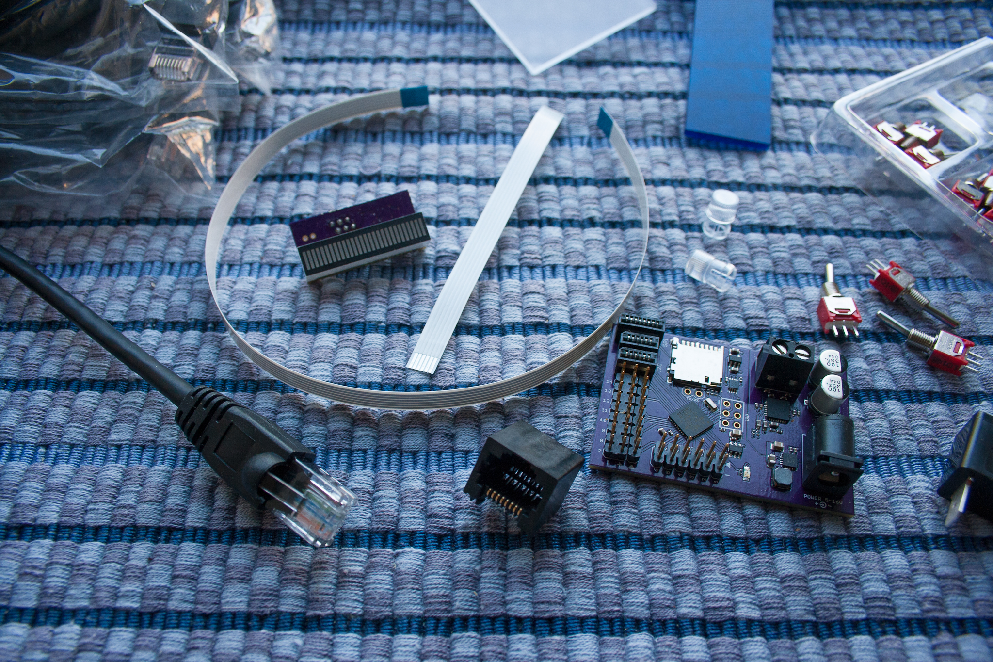
Just got in the new connectors and ribbon cable for the slo-blo and cyclotron LEDs! 

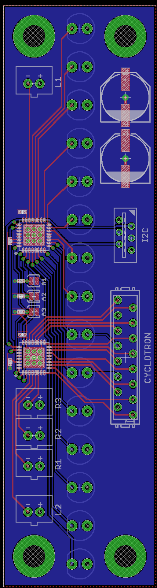
The cyclotron LEDs will be attached to a 16p cable that splits into four at the end while the slo-blo pictured above above is just a single six inch long 4p cable. 

The six pin cable above is one of the old kit’s ribbon cables.  I placed it there as a size reference so you can see just how much smaller the new ribbon cable connectors are. 

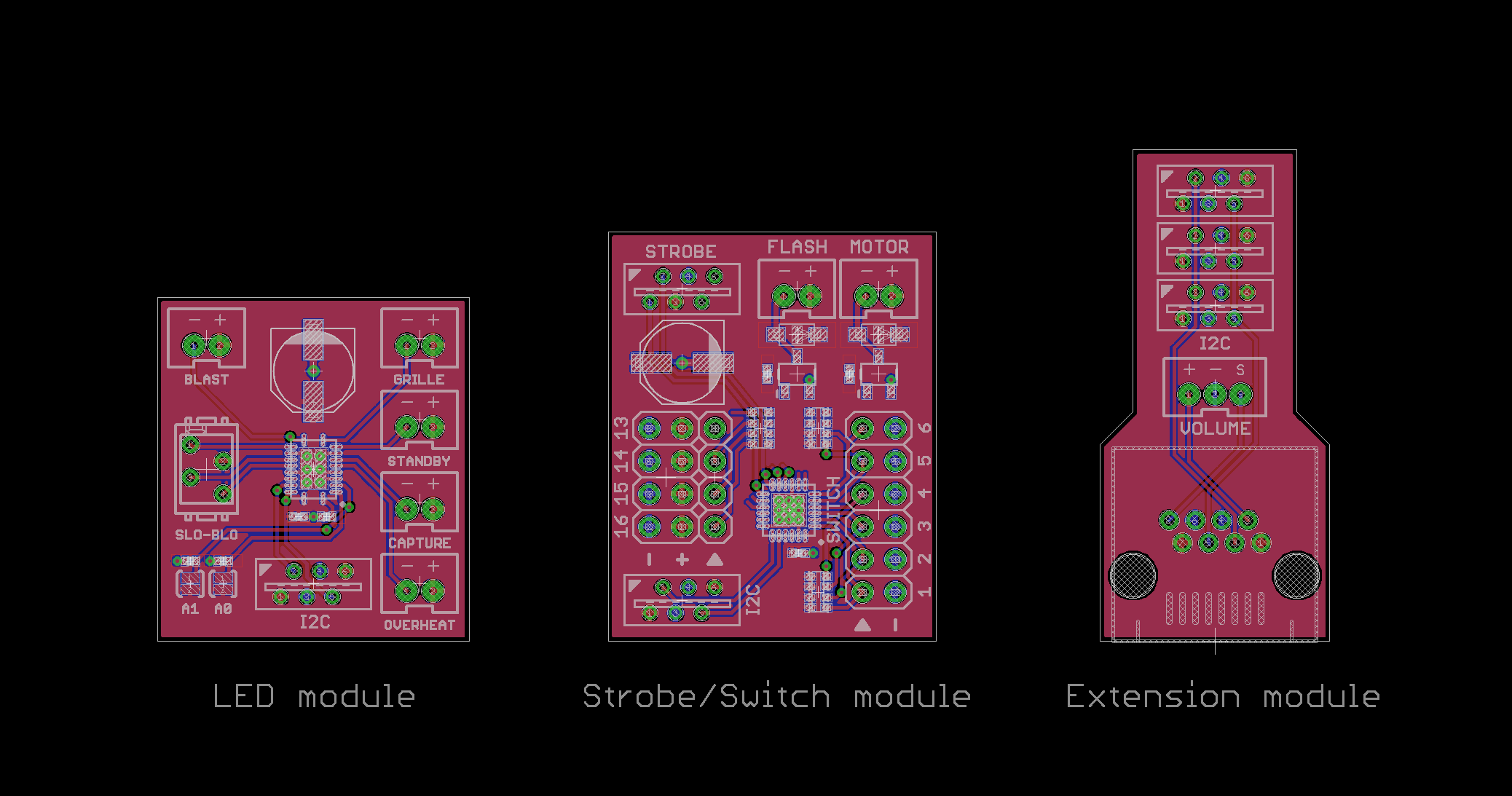
Only the cyclotron and slo-blo LEDs will be attached with ribbon cables.  Other individual LEDs will use 2p JST PH connectors, and all the modules will connect with the 6p flat flex cables seen in previous updates.

Positron Thrower PCB progress

thrower-081In addition to the Pixel I’ve been hard at work on the Positron Proton Pack kit.  What you see here are the near-final designs for the boards which will go in the thrower.

Unlike the old kit, the new kit uses polarized JST connectors for the LEDs, so you can’t plug them in backwards, and they’re clearly labeled to make it easy tell which one goes where.  The color changing slo-blo LED also features a polarized ribbon connector like the one which will be used on the Powercell module for the RGB LEDs.

The strobe/switch module is packed with features.  Up to six switches can be connected (the kit comes with five, the sixth may eventually be a mode changing switch), and there are four servo-like connectors which can be used to trigger relays or to activate a super bright vent LED.  The module also contains circuitry which can directly drive a vibration motor or two, and/or provide a high current 5V source for an LED flash bulb.   And of course, there is a connector for a supr bright color changing LED strobe.

Finally, the Extension module plugs into the end of the CAT5 cable that carries power and data from the pack to the thrower, and fits neatly inside the handle of the thrower to maximize the space inside the thrower’s body in case you have a tip extension mechanism.  The module has connections for three flat flex cables to connect the two modules above and the bargraph module, and in addition it features a connector for a rotary encoder so you can place a volume control inside the thrower if you wish.  (The same connector can also be found on the Positron itself, so if you want the volume control on the pack nstead, you can do that as well.)

Positron Thrower PCBs

They’re not quite finished yet, but they’re getting there!

thrower

The one on the left connects to the CAT5 cable and the bargraph, LED module, strobe, vibration motor, and switches then connect to it.

The one in the center is the new LED module for driving the 5mm LEDs in the thrower, including one for the vent should I decide to offer a lower priced kit that forgoes the new and expensive super bright LED for the vent.

And the board on the right is the old LED module, for size reference.  The new boards are only 1″ wide!

Positron Powercell

positron-powercell

Just finished the layout for the Positron Proton Pack Kit’s powercell!

The mounting holes have the same spacing as on the original powercell, but they’re now mirrored on the other side as well.

The cyclotron’s RGB LEDs are attached directly to the powercell via a 16 pin ribbon cable with a new low profile connector, which is polarized so it can’t be plugged in the wrong way.

There are also five locations for optional JST connectors for the rib LEDs, as seen on the video game pack.  These connectors are also polarized.

The powercell connects to the positron via the FFC connector labeled I2C.  The cable will only mate with the contacts on one side, so it too protects against accidentally plugging the cable in the wrong way.

A1, A2, and A3 are solder jumper pads for setting the address of the board.  You won’t need to change these, as the board will have the correct default address for the kit, but if I ever need to add another powercell to someone’s kit, these pads allow the two to be addressed individually if need be.

The Positron!

layout-prototype2b

It has a name!

What you see above is the latest revision of my proton pack / trap kit, which I will be having manufactured soon.

The biggest change is that I’ve decided to use Cat5 cable for the connection between the thrower and pack. This change was necessary because the new strobes are power hungry and it turned out the flat flex cable (FFC) couldn’t carry as much current as I wanted.  The flat flex will still be used to connect the bargraph and the powercell, but the bargraph will plug into a module with a short FFC that connects to the Cat5 inside the thrower.

I’ve already ordered this new cable, along with with the micro switches for the thrower, and lenses for the powercell, cyclotron, and slo-blo, and a heavy duty Arcoelectric power switch.   The cable and micro switches are included with the kit, but the lenses and heavy duty switch will be extra.  (I intend to offer a wire harness with quick connects to go with the switch eventually so you won’t need to solder anything. )

Here’s some photos of those:

IMG_2149IMG_2152IMG_2155IMG_2164IMG_2158

Proton Pack Kit 2.0

Hey guys!

The first prototype came in last week.  I’ve already ported most of the code to it, and the on-board 40W amplifier works great!

IMG_1960IMG_1934IMG_1927

I haven’t yet updated the code to animate the new bargraph, but I’ll get to that soon, and when I do I’ll post a video!